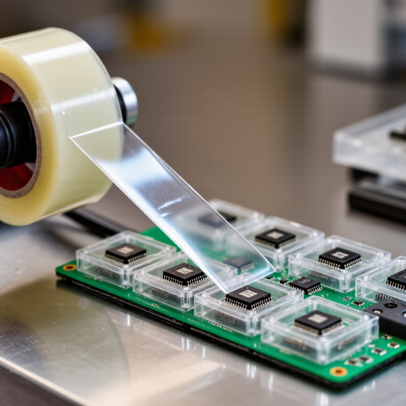
| Primary purpose | Seals the pocket of a carrier tape while allowing controlled opening during component feeding. | Heat activates the sealant layer on the cover tape and bonds it to the carrier tape flange. | Protects components from falling out, dust, moisture, and handling damage. |
| Typical tape construction | Transparent or translucent multilayer film, commonly including a polyester support layer and a heat-sealable polymer layer. | The support layer provides dimensional stability, while the sealant layer softens under heat and forms the bond. | The layered structure balances strength, visibility, sealing performance, and peelability. |
| Common carrier-tape compatibility | Paper, polystyrene, polyester, and polycarbonate carrier tapes, depending on the cover-tape sealant system. | The sealant is selected to wet and bond with the carrier-tape flange without damaging the pocket or components. | Correct material matching reduces weak seals, excessive adhesion, and tape delamination. |
| Typical sealing temperature | Approximately 120–180 °C as an initial process range; the exact value depends on the sealant and carrier tape. | A heated sealing shoe or roller transfers controlled heat through the cover tape to the sealing interface. | Insufficient heat can cause seal failure, while excessive heat may deform the carrier tape or damage heat-sensitive parts. |
| Typical dwell time | Often about 0.5–2.0 seconds during laboratory or line setup; production settings vary by equipment speed and materials. | The tape remains under heat and pressure long enough for the sealant to soften, flow, and bond. | Dwell time affects bond formation, line speed, and the consistency of the peel force. |
| Sealing pressure | A controlled, uniform line pressure is required; the correct setting depends on tape width, equipment, and substrate. | Pressure brings the softened sealant into continuous contact with the carrier-tape flange. | Uneven pressure can create channels, weak areas, wrinkles, or inconsistent opening behavior. |
| Peel strength | A commonly targeted range is approximately 0.5–1.5 N per 15 mm, subject to the applicable specification and application. | The sealant is engineered to hold during transport but separate at a controlled force when the feeder opens the tape. | Too little peel strength risks accidental opening; too much can interrupt feeding or dislodge small components. |
| Opening direction | Peel behavior may be designed for a specified angle, commonly evaluated at approximately 165°–180° in testing. | The cover tape peels away from the carrier flange rather than tearing through the pocket. | Predictable peeling supports stable component presentation and reduces tape fragments. |
| Component visibility | Transparent films allow visual inspection of pocket occupancy, orientation, and component condition. | Light passes through the clear support and sealant layers before the tape is removed. | Visibility helps detect missing, shifted, or incorrectly oriented components before assembly. |
| Moisture and dust protection | A continuous seal helps limit exposure to airborne particles and ambient humidity during storage and transport. | The bonded interface closes the pocket opening along the carrier-tape flange. | Cleaner pockets improve feeding reliability and help protect sensitive components before placement. |
| Process-control checks | Check temperature, pressure, dwell time, alignment, peel force, wrinkles, and seal continuity. | Each variable influences the heat-transfer and bonding cycle at the seal interface. | Routine checks reduce production stoppages, component loss, and inconsistent feeder performance. |
| Main failure modes | Weak seal, excessive peel force, wrinkling, channel leaks, edge lifting, delamination, or carrier deformation. | Failures usually result from incorrect temperature, pressure, speed, alignment, contamination, or material pairing. | Identifying the failure mode helps determine whether to adjust the process or select a different tape construction. |