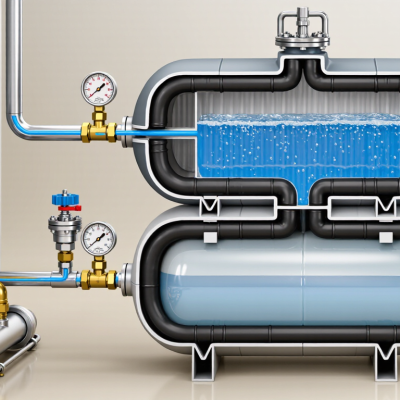
| Primary Function | Absorbs the increase in water volume caused by heating in a closed-loop plumbing or hydronic heating system. | The vessel helps limit pressure fluctuations and reduces discharge through the pressure-relief valve. |
| Common Applications | Closed-loop hydronic heating, chilled-water systems, domestic hot-water systems, solar thermal systems, and process-water circuits. | The vessel must be approved and rated for the specific fluid, temperature, pressure, and installation environment. |
| Construction | A sealed steel tank divided by a flexible diaphragm or bladder into a water side and a pre-charged gas side. | The diaphragm or bladder prevents direct contact between the system water and the gas charge in standard designs. |
| Water Expansion | Water expands as temperature rises. Between approximately 10°C and 80°C, water volume increases by about 2.9%. | The required vessel size depends on the total system water volume and the operating temperature range. |
| Key Sizing Inputs | Total system water volume, minimum system temperature, maximum operating temperature, initial fill pressure, maximum allowable pressure, and vessel pre-charge. | A larger system volume or wider temperature range generally requires a larger vessel. |
| Basic Expansion Calculation | Expansion volume = system water volume × water-volume expansion fraction. | For example, 300 L of water heated from 10°C to 80°C expands by approximately 8.7 L before vessel pressure effects are considered. |
| Illustrative Vessel Estimate | For a 300 L hydronic system with an approximately 8.7 L expansion volume, a vessel nominally around 18–25 L may be required, depending on pressure settings and the manufacturer’s sizing method. | This is an illustrative range, not a final selection. Confirm the result using the vessel manufacturer’s technical data and local code requirements. |
| Typical Pre-Charge Setting | Often set near the required cold fill pressure, commonly about 1.0–1.5 bar in small closed hydronic systems. | The exact setting depends on building height, static pressure, system design, and the vessel manufacturer’s instructions. |
| Cold Fill Pressure | A common design approach is to maintain sufficient pressure at the highest point, often adding approximately 0.3 bar safety margin above the static head requirement. | Do not exceed the rating of the lowest-pressure component in the system. |
| Maximum Working Pressure | Common vessel ratings include approximately 3 bar, 6 bar, 8 bar, or 10 bar, depending on the application and design. | The vessel rating must be equal to or greater than the system’s maximum allowable working pressure. |
| Maximum Temperature | Heating-system vessels are commonly designed for water temperatures around 90°C to 120°C, while potable-water vessels may have different limits. | Always verify the vessel’s temperature rating, especially in solar thermal and high-temperature heating systems. |
| Installation Location | Install on the system side where pressure changes need to be controlled, commonly near the boiler, heat source, water heater, or pump connection point. | Follow the approved system layout and allow sufficient clearance for inspection, replacement, and service access. |
| Connection Orientation | Many vessels can be installed vertically or horizontally when properly supported, but the permitted orientation depends on the design. | Use a support bracket or suitable mounting method. Do not allow unsupported pipework to carry the vessel’s full weight. |
| Isolation and Drainage | A service isolation valve and a means of safely draining or depressurizing the vessel are recommended where permitted by the system design. | The isolation arrangement must not compromise the function of the pressure-relief system. |
| Pressure-Relief Protection | A correctly sized and rated pressure-relief valve is required to protect the closed system from overpressure. | Never block, cap, or isolate a pressure-relief valve from the system unless an approved equivalent safety arrangement is provided. |
| Pre-Charge Inspection | Measure gas pre-charge with the water side fully depressurized and isolated from system pressure. | Measuring pre-charge while the vessel is pressurized with water produces an unreliable reading. |
| Recommended Maintenance Interval | Inspect at least annually; commercial, high-temperature, or critical systems may require more frequent checks. | Record pressure readings, leakage observations, relief-valve activity, and any changes in system pressure. |
| Common Failure Signs | Frequent pressure-relief discharge, rapidly changing pressure, repeated need for system top-up, water at the gas valve, corrosion, or unusual noise. | Water escaping from the air valve may indicate a failed diaphragm or bladder and usually requires vessel replacement. |
| Replacement Criteria | Replace the vessel if the diaphragm or bladder has failed, the shell is corroded or damaged, the vessel cannot hold its pre-charge, or its pressure rating is unsuitable. | Select a replacement with compatible volume, connection size, pressure rating, temperature rating, and fluid approval. |
| Safety Requirement | Installation, testing, and servicing should be carried out by a qualified professional in accordance with applicable plumbing, heating, pressure-equipment, and building regulations. | Fully isolate, cool, drain, and depressurize the system before servicing the vessel. |