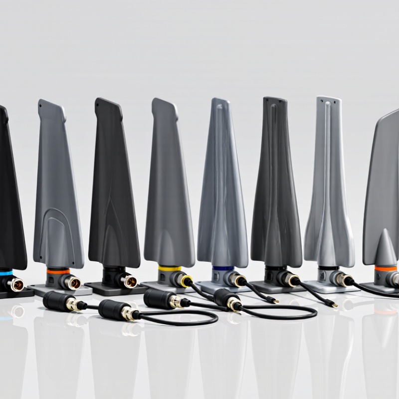
| 1 | Sub-GHz telemetry blade | 433 MHz, where permitted | Low-rate command, status, and sensor telemetry | Usually linear; broad, near-omnidirectional coverage when unobstructed | The longer wavelength generally calls for a physically larger antenna. Keep it clear of carbon-fiber structures, batteries, and wiring. | Can support useful link margins at low data rates, but regional radio rules and antenna size can constrain the design. |
| 2 | 868 MHz telemetry blade | 868 MHz band, in regions where applicable | Command and telemetry links for long-endurance or mapping aircraft | Typically linear; coverage depends on mounting angle and airframe shadowing | A vertical or suitably angled external mount can help maintain clearance from conductive and carbon-fiber components. | Suitable channel availability and permitted power vary by country; do not assume it is interchangeable with 915 MHz equipment. |
| 3 | 915 MHz telemetry blade | 902–928 MHz in some regions | Telemetry and command links where the local allocation supports this band | Usually linear; broad azimuth coverage is possible with a clear installation | Check the blade’s ground-plane requirements and avoid placing it directly behind the battery or inside a conductive enclosure. | Regional frequency limits, channel plans, and power rules apply; performance depends on antenna matching in the installed airframe. |
| 4 | 1.2 GHz video or data blade | Commonly around 1.2–1.3 GHz, subject to allocation | Video or data links using an authorized regional frequency plan | Often linear; directional options may be used where the mission and link geometry allow | Confirm clearance from GNSS and other onboard radios, and test for receiver desensitization or harmonic interference. | Band availability differs substantially by region and service; compatibility with the transmitter and receiver is essential. |
| 5 | 2.4 GHz control and telemetry blade | 2.4 GHz ISM band | Short- to medium-range command, control, and general-purpose data | Commonly linear; antenna orientation should be coordinated with the ground station | Small form factors suit compact airframes, but carbon-fiber skins and nearby electronics can detune or block the antenna. | Widely used and compact, but the band can be congested and is subject to local rules and equipment limits. |
| 6 | 5.8 GHz video blade | 5.8 GHz band, where permitted | High-throughput video links and short-range payload data | Linear or circular, depending on the radio system; higher-frequency paths are more sensitive to obstruction | Use a clear mounting position and account for airframe blockage during banked turns. Verify separation from other antennas. | Small antenna size and substantial bandwidth are possible, but range and penetration are generally more sensitive to obstructions. |
| 7 | Dual-band 2.4/5.8 GHz blade | 2.4 GHz and 5.8 GHz | Platforms that need one antenna assembly for compatible control, data, or video radios | Depends on the design; verify polarization and pattern separately for each band | Check whether the antenna has separate feeds or a shared feed, and confirm that the radio supports the same arrangement. | Can reduce installation space, but a dual-band label does not guarantee equal performance on both bands. |
| 8 | Cellular sub-6 GHz blade | Multiple cellular bands, depending on the antenna and region | Network-connected command, telemetry, or payload data within cellular coverage | Often linear; MIMO systems require multiple suitably separated antenna elements | For MIMO, follow the modem’s antenna-port and isolation requirements. Test installation effects from the battery, frame, and payload. | Coverage and supported bands depend on the modem, carrier, and operating area; cellular connectivity is not guaranteed everywhere. |
| 9 | GNSS L1 active blade | GPS L1 at 1575.42 MHz; other compatible constellations may share nearby L1/E1 bands | Positioning and navigation on aircraft using a compatible GNSS receiver | Typically right-hand circular polarization for GNSS reception; generally designed for sky-facing installation | Mount with a clear view of the sky and follow the antenna’s ground-plane and active-bias requirements. Keep it away from noisy electronics. | Compact L1 reception can suit many platforms, but it does not provide the additional frequency measurements available from multi-band systems. |
| 10 | Multi-band GNSS blade or low-profile antenna assembly | Common combinations include L1/E1, L2, and/or L5/E5 bands | Higher-precision positioning or applications that benefit from multi-frequency GNSS measurements | Typically right-hand circular polarization; performance depends on the receiver and antenna configuration | Check supported constellations, active-element power, ground-plane needs, and available mounting area; validate the complete receiver-antenna system. | Multi-frequency capability can improve measurement options, but it may increase size, cost, power needs, and integration complexity. |