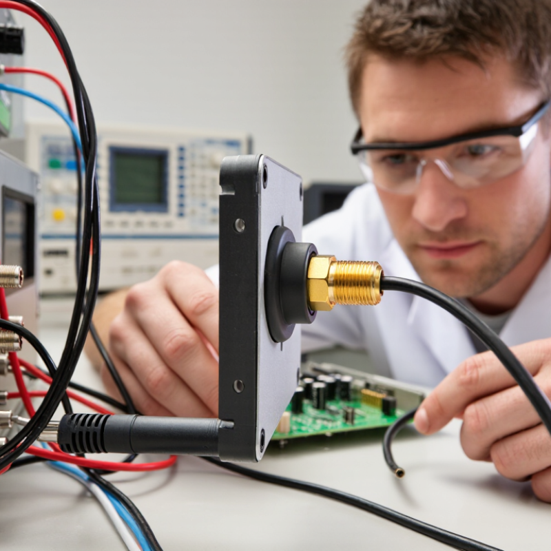
| 1. Confirm connector compatibility | Check that both connectors are SMA, not a visually similar reverse-polarity SMA type. Confirm the required gender and interface before connecting. | Incompatible connector types can prevent proper contact, damage connector parts, or leave the RF path open. | Compare the connector specification and inspect the center contact before mating. Never force a connection. |
| 2. Tighten to the specified torque | Use a calibrated torque wrench when the connector specification calls for one. Follow the torque value provided for that specific connector; avoid overtightening. | Correct tightening helps maintain consistent electrical contact. Excessive force can damage threads, the center contact, or the connector body. | Check the connector or equipment documentation for the applicable torque value and tighten the coupling nut, not the cable. |
| 3. Keep mating surfaces clean and dry | Inspect the center contact and mating face for dust, moisture, corrosion, or damage. Clean only with an appropriate lint-free method and allow surfaces to dry. | Contamination can increase contact resistance and disrupt the RF connection, contributing to signal loss or unstable readings. | Inspect under good lighting before mating. Replace a connector with bent, loose, or visibly damaged contacts. |
| 4. Prevent cable strain and sharp bends | Route the coaxial cable without twisting or pulling on the SMA connector. Keep bends within the cable manufacturer’s minimum bend-radius guidance. | Strain and tight bends can deform the cable, impair shielding, or loosen the connector over time. | Check that the cable is supported near the antenna and that the connector is not carrying the cable’s weight. |
| 5. Minimize adapters and cable length | Use the shortest practical length of suitable coax and remove unnecessary adapters or couplers from the RF path. | Every cable run and added connection contributes some insertion loss, which generally increases with frequency and cable length. | Review the signal path and, where needed, measure insertion loss across the operating frequency range. |
| 6. Use a 50-ohm RF path | Match the antenna, cable, connectors, and radio system to the specified impedance, commonly 50 ohms for SMA RF equipment. | An impedance mismatch can cause reflections and reduce the power delivered to or received from the antenna. | Verify component specifications and measure return loss or VSWR with suitable test equipment at the operating frequency. |
| 7. Protect outdoor connections appropriately | For outdoor installations, use weather protection suited to the connector and environment. Keep moisture protection from contaminating the electrical mating surfaces. | Water ingress and corrosion can degrade the connection and cause performance to worsen over time. | Follow the equipment’s sealing instructions and periodically inspect the connection for moisture, corrosion, or damaged seals. |