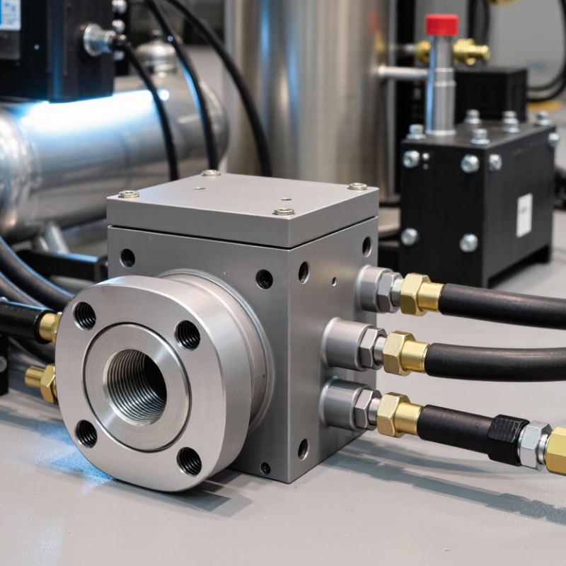
| Definition | A relief valve block is a compact manifold or valve assembly used to connect, isolate, test, drain, or route flow around a pressure relief valve. | It may contain isolation valves, a relief valve connection, a test port, a drain port, and internal passages. | It supports safe and controlled pressure protection but does not replace the relief valve itself. |
| Primary Function | To provide a controlled connection between protected equipment, the relief valve, and the discharge or return line. | The block can simplify installation and reduce the number of separate fittings and pipe joints. | Fewer connections can reduce potential leak points and make pressure-protection equipment easier to inspect. |
| Pressure-Sensing Point | The inlet passage exposes the relief valve to the pressure of the protected system. | The sensing pressure should be taken from a suitable point where pressure is representative of the equipment being protected. | Accurate sensing helps the relief valve open at its specified set pressure. |
| Normal Operating Condition | The relief valve remains closed while system pressure stays below its set pressure. | The block normally allows the protected system to operate without intentional discharge through the relief path. | Keeping the relief valve closed prevents unnecessary loss of fluid and maintains normal system operation. |
| Overpressure Condition | When system pressure reaches the valve’s set pressure, the relief valve opens to discharge or redirect excess fluid. | Opening pressure, blowdown, reseating pressure, and flow capacity depend on the valve design and service conditions. | The relief path limits pressure rise and helps prevent damage caused by excessive pressure. |
| Pressure-Relief Element | The relief valve uses a spring, pilot mechanism, or another calibrated force to keep the valve closed until the set pressure is reached. | Common relief valve designs include spring-loaded and pilot-operated types. | The calibrated mechanism determines when the valve opens and how it responds to changing pressure. |
| Isolation Function | An isolation valve may allow the relief valve to be separated from the process for maintenance or replacement. | Isolation arrangements require careful design because an incorrectly closed valve can disconnect the equipment from overpressure protection. | Isolation must not unintentionally disable the only available pressure-relief path during operation. |
| Testing Function | A test port can be used to verify valve response, pressure indication, or the condition of connected passages. | Testing may be performed with suitable calibrated equipment and according to the applicable maintenance procedure. | Testing confirms that the relief valve and its connection remain capable of responding at the required pressure. |
| Drain or Vent Port | A drain or vent connection can remove trapped liquid, gas, or residual pressure from the block during servicing. | The port should discharge to a safe location compatible with the process fluid. | Controlled depressurization reduces the risk of unexpected release during inspection or maintenance. |
| Flow Direction | Flow normally enters from the protected system and exits through the relief valve discharge path when the valve opens. | Directional arrows, port markings, or installation drawings identify the intended flow route. | Correct orientation helps prevent restricted flow, improper valve operation, and installation-related pressure errors. |
| Materials | Block materials are selected according to pressure, temperature, fluid compatibility, corrosion exposure, and mechanical requirements. | Common material categories include carbon steel, stainless steel, alloy steel, and other engineered alloys. | Material compatibility helps preserve pressure integrity and prevent corrosion-related leakage or failure. |
| Connections | Connections may be threaded, flanged, socket-welded, butt-welded, or otherwise specified for the installation. | Connection selection depends on nominal size, pressure class, temperature, fluid type, and applicable engineering standards. | Properly rated connections prevent leakage and maintain the required pressure boundary. |
| Pressure Rating | The block and every connected component must be rated for the maximum allowable working pressure and temperature of the service. | The lowest-rated component generally limits the allowable operating conditions of the assembly. | Correct pressure and temperature ratings help prevent mechanical rupture and loss of containment. |
| Back Pressure | Pressure existing at the relief valve outlet can affect opening behavior and discharge capacity. | Back pressure may be built-up by the discharge system or superimposed from another pressure source. | The block and discharge arrangement should be designed so back pressure remains within the relief valve’s allowable limits. |
| Flow Capacity | The relief path must pass enough fluid to reduce or limit pressure under the identified overpressure scenario. | Capacity depends on valve orifice area, fluid properties, upstream pressure, downstream pressure, and temperature. | An undersized or restricted path may fail to provide adequate pressure protection. |
| Typical Applications | Relief valve blocks are used in hydraulic, pneumatic, process, instrumentation, and industrial pressure systems. | Applications may include pressure vessels, pump systems, gas lines, hydraulic power units, and test equipment. | The block provides a compact interface for protecting equipment from pressure exceeding its design limits. |
| Maintenance Requirements | Maintenance can include leakage checks, connection inspection, cleaning, calibration verification, and relief valve testing. | Maintenance intervals should be based on service severity, operating history, regulatory requirements, and the equipment manufacturer’s instructions. | Regular inspection helps ensure that the pressure-protection function remains available when required. |
| Main Safety Rule | The protected equipment must not be operated with its only relief path unintentionally blocked or isolated. | Isolation devices should be secured, interlocked, monitored, or managed by an approved operating procedure where required. | Maintaining an available relief path is essential for preventing uncontrolled overpressure. |