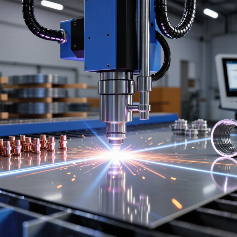
| 1 | Machine Setup | The operator selects the cutting method, installs the appropriate nozzle or cutting head, and loads the material specification into the control system. | Common methods include laser, plasma, waterjet, and oxy-fuel cutting. The choice depends on material type, thickness, required accuracy, and production volume. | The machine is configured for the workpiece and the intended cut profile. |
| 2 | Material Positioning | The sheet, plate, pipe, or fitting is placed on the worktable or fixture. Clamps, supports, or a rotary attachment may be used to prevent movement. | Correct alignment is essential. The workpiece must be stable, accessible to the cutting head, and positioned within the machine's travel range. | The material is securely positioned and referenced to the machine coordinate system. |
| 3 | Program Loading | A digital cutting file is imported or created. The controller converts the design into toolpaths that define the nozzle movement and cutting sequence. | Frequently used file formats include DXF and other CAD/CAM formats. The program may include lead-ins, lead-outs, pierce points, and nesting information. | The machine has a defined path for producing the required opening, contour, or profile. |
| 4 | Nozzle Calibration | The cutting head establishes the correct distance, focus, or stand-off from the material surface. Sensors may detect height or surface position automatically. | Laser cutting commonly requires focal-position control. Plasma and oxy-fuel systems require an appropriate stand-off distance and consumable condition. | The energy or cutting stream is directed at the correct location for a stable cut. |
| 5 | Piercing or Entry | The machine begins the cut by piercing the material or entering from an edge. The controller manages the initial energy, pressure, or flame sequence. | Pierce time and power depend on the cutting process and material thickness. A lead-in can help keep the initial pierce mark away from the finished edge. | A controlled starting point is created without unnecessarily damaging the final contour. |
| 6 | Contour Cutting | The nozzle moves along the programmed path while the cutting beam, arc, waterjet, or flame removes material from the kerf. | Cut quality is influenced by feed rate, energy or gas settings, nozzle condition, material grade, thickness, and machine rigidity. | The desired hole, slot, edge, or three-dimensional nozzle profile is separated from the surrounding material. |
| 7 | Assist Gas or Cutting Medium | A process medium may eject molten material, cool the cut, support combustion, or remove debris from the kerf. | Laser and plasma systems may use compressed gases such as air, nitrogen, or oxygen. Waterjet systems use pressurized water, sometimes with abrasive particles. | Dross, slag, and heat-affected effects are controlled to support a cleaner cut. |
| 8 | Path Completion | The machine completes the programmed contour and applies the programmed lead-out or shutdown sequence. | The controller may reduce energy before stopping and may return the head to a safe position. Closed-loop control can help maintain consistent motion. | The finished part or opening is released from the programmed path. |
| 9 | Part Removal and Cleaning | The operator removes the cut component and clears slag, dross, abrasive, or loose remnants from the work area. | Deburring tools, brushes, compressed air, or secondary machining may be used depending on the required edge finish. | The component is prepared for inspection, welding, assembly, or further finishing. |
| 10 | Quality Inspection | Critical dimensions, edge condition, hole location, taper, and surface finish are checked against the drawing or production specification. | Inspection may use calipers, gauges, templates, coordinate measuring equipment, or optical measurement systems. | The operator verifies whether the cut meets dimensional and quality requirements. |
| 11 | Routine Maintenance | The nozzle, lens or electrode components, gas lines, filters, guides, and work surface are inspected and serviced as required. | Wear, contamination, misalignment, unstable gas flow, and damaged consumables can reduce accuracy and cut quality. | Regular maintenance helps preserve repeatability, safety, and operating efficiency. |