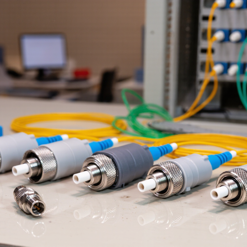
| Optical Attenuator Fundamentals |
| Primary Function | Reduces optical power by a specified amount, measured in decibels (dB). | Prevents excessive input power from causing receiver overload, measurement errors, or nonlinear effects. | Choose an attenuation value that keeps the received power within the equipment's specified operating range. |
| Attenuation Principle | Absorption, reflection, scattering, controlled air gap, or a combination of optical and mechanical methods. | The principle affects insertion loss, return loss, wavelength behavior, and power-handling capability. | For precision links, prioritize stable attenuation and low reflection. For simple testing, a fixed attenuator may be sufficient. |
| Attenuation Unit | Decibel (dB); optical power transmission is commonly expressed as a percentage or ratio. | A logarithmic scale makes it easier to specify large power reductions. | Confirm whether the stated value is nominal attenuation or measured attenuation at a specific wavelength. |
| Typical Applications | Receiver overload protection, optical power equalization, network testing, link-margin verification, and instrument calibration. | Different applications require different levels of adjustment, stability, and repeatability. | Define the application before selecting the attenuator type and attenuation range. |
| Comparison of Common Optical Attenuator Types |
| Fixed Attenuator | Common nominal values include 1, 3, 5, 10, 15, and 20 dB. | Provides a constant reduction in optical power with a simple and compact structure. | Best for permanent installation when the required attenuation is known and does not need adjustment. |
| Variable Optical Attenuator | Typical adjustable ranges include 0–10 dB, 0–20 dB, or wider ranges depending on the design. | Allows optical power to be tuned during testing, commissioning, or changing network conditions. | Choose a model with sufficient adjustment range, fine resolution, low drift, and repeatable settings. |
| In-Line Attenuator | Installed directly in the optical path using mating connectors or a short optical assembly. | Offers convenient installation without requiring a separate optical module or equipment rack. | Match the connector interface, fiber type, polarity, and environmental rating to the link. |
| Connector-Style Attenuator | Usually available as a connector-mounted component with a predefined attenuation value. | Provides a quick plug-in solution for reducing power at a specific connection point. | Verify connector compatibility and ensure that repeated mating will not compromise cleanliness or return loss. |
| Bulkhead Attenuator | Mounted through a panel or adapter plate and connected from both sides. | Supports organized, semi-permanent installation in distribution panels and test fixtures. | Consider panel dimensions, connector orientation, mounting method, and cable-management requirements. |
| Motorized or Programmable Attenuator | Electronically controlled attenuation with software or automated test-system integration. | Supports repeatable remote adjustment and automated measurement sequences. | Check control interface, positioning repeatability, switching speed, power supply, and automation compatibility. |
| Key Technical Parameters |
| Attenuation Range | Fixed values or an adjustable range stated in dB. | Determines whether the component can achieve the required optical power level. | Select a range that covers the maximum expected attenuation while retaining useful adjustment resolution. |
| Attenuation Accuracy | Specified as the difference between the actual and nominal attenuation, commonly expressed in dB. | Influences power-budget calculations and the accuracy of receiver-sensitivity tests. | Use tighter accuracy for laboratory measurements, calibration, and high-precision link testing. |
| Operating Wavelength | Common fiber-optic windows include approximately 850 nm, 1310 nm, and 1550 nm. | Attenuation can vary with wavelength, especially in designs that are not broadband. | Choose a wavelength-compatible attenuator and review its performance across the complete operating band. |
| Wavelength Bandwidth | May be single-window, dual-window, or broadband across multiple telecom or datacom bands. | A wider bandwidth is important for systems using wavelength-division multiplexing or multiple transceiver types. | Confirm the attenuation flatness across all wavelengths used by the system. |
| Insertion Loss | Additional loss introduced by the component beyond its intended attenuation. | Excess insertion loss reduces the available optical power budget. | Compare the specified insertion loss with the link budget, especially for short-reach systems with limited margin. |
| Return Loss | Reflection performance expressed in decibels; higher return-loss values generally indicate lower reflected power. | Reflections can affect lasers, coherent systems, interferometric measurements, and sensitive receivers. | Choose a higher-return-loss design when the transmitter or measurement system is sensitive to optical reflections. |
| Fiber Type | Single-mode fiber is commonly used for long-distance and wavelength-specific links; multimode fiber is commonly used for short-reach datacom links. | Mode mismatch can create coupling loss and measurement uncertainty. | Match the attenuator to the fiber core, mode-field characteristics, and system transmission technology. |
| Maximum Optical Input Power | Specified by the manufacturer for continuous or peak optical power conditions. | Exceeding the rating may cause heating, drift, permanent damage, or unreliable attenuation. | Choose a power rating above the highest expected input level and consider the operating temperature. |
| Polarization Dependence | Variation in attenuation caused by changes in the polarization state of the input light. | Low polarization dependence is important for polarization-sensitive and precision measurement systems. | Review polarization-dependent loss when testing coherent, polarization-maintaining, or high-accuracy systems. |
| Temperature Stability | Change in attenuation or other optical parameters over the specified operating temperature range. | Temperature changes can alter component alignment and attenuation accuracy. | Select a thermally stable design for outdoor cabinets, industrial environments, and long-duration measurements. |
| Connector Interface | Common interfaces include LC, SC, ST, FC, and connectorless fiber configurations. | Mechanical incompatibility prevents installation and may increase coupling loss or reflection. | Match connector type, polish style, key orientation, and adapter requirements before ordering. |
| Environmental Protection | May include indoor, outdoor, dust-resistant, moisture-resistant, or ruggedized construction. | Contamination, vibration, humidity, and temperature cycling can affect optical performance. | Choose an environmental rating suitable for the actual installation location rather than the laboratory specification alone. |
| Practical Selection Guide |
| Known and Constant Power Reduction | Use a fixed attenuator with the required nominal dB value. | Minimizes complexity and provides a stable, economical solution. | Verify attenuation accuracy, wavelength, connector type, and power rating. |
| Frequent Testing or Calibration | Use a variable or programmable attenuator with a suitable adjustment range. | Allows multiple test conditions to be created without changing components. | Prioritize repeatability, resolution, calibration capability, and control integration. |
| High-Reflection-Sensitivity System | Use an attenuator with strong return-loss performance and low reflected power. | Reduces interference and instability caused by back reflections. | Review return loss, polarization dependence, and connector end-face quality. |
| Multiple Wavelengths | Use a broadband or wavelength-qualified attenuator. | Helps maintain predictable attenuation across the entire operating band. | Check wavelength-dependent attenuation and flatness rather than relying on a single test wavelength. |
| High Optical Power | Use a high-power-rated attenuator designed for the expected continuous-wave or peak input. | Reduces the risk of thermal damage and attenuation drift. | Include operating temperature, duty cycle, beam conditions, and safety limits in the selection process. |
| Limited Link Budget | Use the lowest attenuation value that achieves receiver protection or test objectives. | Every additional dB reduces the available power margin. | Calculate transmitter output, connector loss, splice loss, fiber loss, attenuator loss, and receiver sensitivity together. |
| Final Verification Before Installation | Confirm attenuation, wavelength, connector interface, fiber type, power handling, return loss, and environmental requirements. | A technically suitable attenuation value can still be unusable if the mechanical or environmental specifications do not match. | Always compare the component specification with the complete optical link budget and the equipment manufacturer's allowable input-power range. |