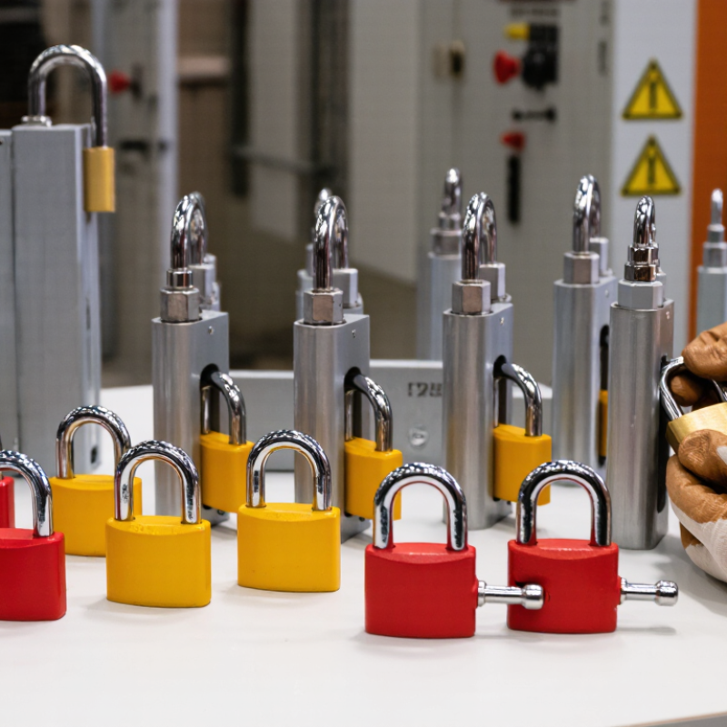
| Standard safety padlock | Provides personal control over an isolated energy source. | Lockout hasps, valve covers, breaker lockouts, and cable devices. | Usually one key per lock; shackle diameter commonly 4–6 mm. | Steel or aluminum body; steel, stainless steel, or aluminum shackle. | Individual employee lockout in routine maintenance. | Check shackle clearance, corrosion resistance, key control, and identification options. |
| Non-conductive safety padlock | Reduces the risk of an electrical path through the lock body or shackle. | Electrical disconnect lockouts and insulated electrical panels. | Typically one personal lock; common shackle diameter 4–6 mm. | Engineering polymer body with non-conductive shackle options. | Electrical maintenance where insulation is an additional control measure. | Verify the manufacturer’s electrical-use rating; non-conductive does not replace de-energization or test procedures. |
| Lockout hasp | Allows multiple authorized workers to apply personal padlocks to one isolation point. | Disconnect handles, valves, and other points with a suitable attachment opening. | Commonly 4–8 padlock holes; hole diameter often about 8–10 mm. | Zinc-plated steel, stainless steel, or reinforced polymer. | Group maintenance and shift changes. | Confirm hole count, hole diameter, jaw opening, and whether the hasp can be removed while any lock remains attached. |
| Miniature circuit-breaker lockout | Prevents operation of compatible miniature circuit-breaker toggles. | Single-pole, double-pole, or multi-pole breakers, depending on the device design. | Usually accepts one padlock; some designs support a small hasp or multiple devices. | Glass-filled nylon, reinforced polymer, or coated metal components. | Control panels and distribution boards with narrow breaker toggles. | Measure toggle width, profile, spacing, and operating direction; verify compatibility with the exact breaker family. |
| Molded-case circuit-breaker lockout | Secures larger breaker handles that cannot accept miniature-breaker devices. | Wide or oversized molded-case breaker handles. | Usually one padlock per device; some versions accommodate a hasp. | Durable polymer, stainless steel, or coated steel. | Industrial switchboards and high-current distribution equipment. | Check handle dimensions, available clearance, attachment method, and enclosure-door clearance. |
| Universal circuit-breaker lockout | Provides adjustable coverage for several breaker handle designs. | Many single- and multi-pole breaker configurations within the stated size range. | Generally one padlock; some models allow a hasp attachment. | Reinforced polymer with metal adjustment or clamping components. | Facilities with mixed electrical equipment and changing panel inventories. | Compare the adjustable range with the largest and smallest handles; avoid excessive movement after installation. |
| Ball-valve lockout | Stops a quarter-turn ball-valve handle from moving to the open position. | Ball valves with compatible handle thickness and travel geometry. | Commonly one padlock; some designs support two or more locks. | Reinforced nylon, polypropylene, or coated steel. | Pneumatic, hydraulic, water, and process-fluid isolation. | Measure handle length, thickness, stem clearance, and valve size; confirm the device blocks the intended direction. |
| Gate-valve lockout | Encloses or blocks a gate-valve handwheel to prevent operation. | Gate valves within the device’s published handwheel diameter range. | Typically one padlock; group versions may accept multiple locks or a hasp. | Impact-resistant polymer or coated metal. | Large process, utility, and fluid-control valves. | Select by handwheel diameter and depth; allow space for the lock and verify resistance to environmental exposure. |
| Plug-valve lockout | Restricts movement of plug-valve handles or operating levers. | Plug valves with compatible handle shape, size, and rotation path. | Usually one padlock; some adjustable devices support a hasp. | Coated steel, stainless steel, or reinforced polymer. | Gas, chemical, and process piping isolation. | Check handle geometry, rotation angle, pipe clearance, and chemical compatibility. |
| Cable lockout device | Secures irregular, remote, or multiple energy-isolation points with a flexible cable. | Valves, disconnects, switches, and mechanisms that do not accept dedicated lockouts. | Cable lengths commonly range from about 1.8–3.7 m; accepts one or more padlocks depending on the head design. | Stainless steel or galvanized cable with polymer-coated or metal locking head. | Complex machinery and multiple isolation points. | Choose cable length, diameter, flexibility, head capacity, and resistance to cutting or corrosion. |
| Wall-switch or push-button lockout | Prevents operation of selected control buttons, switches, or disconnect controls. | Push buttons, rotary switches, wall switches, and control-station components within the stated dimensions. | Normally one padlock; some covers allow a hasp or two locks. | Transparent or colored polycarbonate, ABS, or reinforced polymer. | Control stations where accidental start-up is a concern. | Verify button or switch diameter, mounting method, visibility, and whether the control can still be accessed from the protected side. |