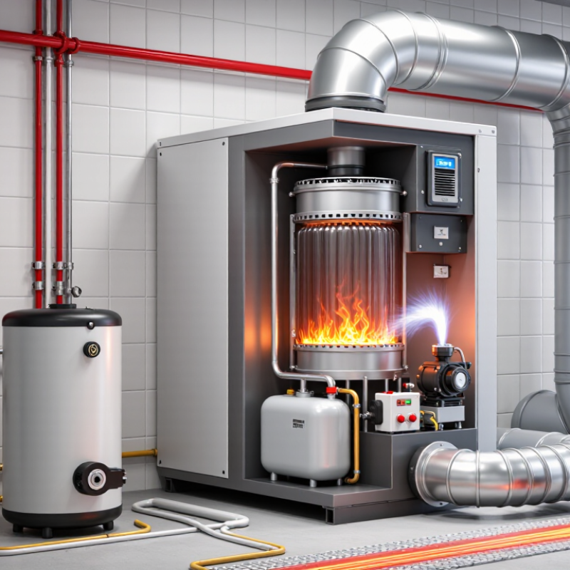
| Step-by-Step Fuel Oil Heating Process |
| 1 | Heat Demand | A thermostat or control system detects that the indoor temperature is below the selected set point and sends a call for heat. | Thermostat, control board, low-voltage wiring | Common residential thermostat settings are approximately 18–24 °C (64–75 °F). | Accurate temperature sensing helps prevent unnecessary burner cycles and fuel consumption. |
| 2 | Safety Verification | The primary control checks operating conditions before ignition, including the burner motor, ignition circuit, and flame-monitoring system. | Primary control, safety limit, flame sensor, motor relay | The burner should not continue firing if a safe flame signal is not detected within the control's programmed trial period. | Safety controls are designed to shut down the burner when ignition or flame detection is unsuccessful. |
| 3 | Fuel Delivery | A fuel pump draws heating oil from the storage tank and sends it through a filter toward the burner nozzle. | Storage tank, fuel line, shutoff valve, fuel filter, fuel pump | Heating-oil burner pump pressure is commonly set in the approximate range of 100–200 psi, depending on burner design and adjustment. | A clean filter and leak-free fuel line are essential for stable fuel flow and reliable combustion. |
| 4 | Fuel Atomization | The burner nozzle converts pressurized liquid oil into a fine spray inside the combustion chamber. | Nozzle, pump, nozzle adapter, combustion head | Nozzle capacity is commonly specified in US gallons per hour; residential sizes often fall below 2.00 US gal/h. | Correct nozzle size and spray pattern are required to match the appliance's rated firing input. |
| 5 | Air Supply | A powered burner fan supplies combustion air and mixes it with the atomized oil spray. | Burner motor, blower wheel, air shutter, combustion head | Airflow must be sufficient for complete combustion without creating excessive draft or unstable flame conditions. | Blocked air inlets, incorrect air settings, or inadequate room ventilation can cause unsafe combustion. |
| 6 | Ignition | An ignition transformer or electronic igniter produces a high-voltage spark that ignites the oil-and-air mixture. | Ignition transformer or igniter, electrodes, burner nozzle | Ignition systems commonly generate several thousand volts to create the spark required for burner startup. | Ignition components should be serviced only after electrical power has been disconnected. |
| 7 | Combustion | The oil burns in the combustion chamber, releasing chemical energy as heat and producing hot combustion gases. | Combustion chamber, burner head, flame-retention head | Heating oil has an energy content of roughly 137,000–140,000 BTU per US gallon, equivalent to about 40 MJ/L. | Proper combustion should produce a stable flame with controlled emissions and minimal soot formation. |
| 8 | Heat Transfer | Hot gases pass through heat-transfer surfaces, warming the air, water, or other heat-transfer medium used by the heating system. | Heat exchanger, flue passages, blower or hydronic heat-transfer circuit | Residential fuel-oil heating appliances commonly have rated seasonal efficiencies from approximately 80% to above 90%, depending on design and operating conditions. | A clean heat exchanger improves heat transfer and reduces the risk of elevated flue-gas temperatures. |
| 9 | Heat Distribution | In a warm-air system, a blower moves heated air through ducts. In a hydronic system, heated water circulates through radiators, baseboards, or radiant tubing. | Blower, ductwork, circulator pump, radiators, baseboards, radiant tubing | Distribution temperatures vary by system; hydronic systems often operate with water temperatures roughly between 60–85 °C (140–185 °F). | Balanced airflow or water circulation helps maintain even room temperatures and reduces system cycling. |
| 10 | Flue-Gas Exhaust | Remaining combustion gases leave the heat exchanger through a flue pipe and chimney or approved venting system. | Flue pipe, draft regulator, chimney or vent, chimney connector | Venting must maintain adequate draft and safely discharge combustion products, including carbon monoxide. | Never operate a fuel-oil heater with damaged, blocked, or improperly installed venting. |
| 11 | Flame Monitoring | A cadmium-sulfide flame sensor or other approved detector confirms that the burner flame remains established. | Flame sensor, primary control, safety lockout | If the control does not detect a valid flame signal, it normally stops the fuel pump and ignition sequence. | Flame monitoring prevents continued fuel delivery when combustion is not occurring correctly. |
| 12 | Thermostat Satisfied | When the desired temperature is reached, the control ends the burner call. The blower or circulator may continue briefly to remove residual heat. | Thermostat, primary control, blower or circulator, post-purge control | Post-purge timing varies by equipment and control settings; it is normally limited to a short period after burner shutdown. | Allowing residual heat to leave the heat exchanger can improve efficiency and protect system components. |
| Key Fuel-Oil Heater Data Dimensions |
| A | Fuel Type | Liquid heating oil, commonly a middle-distillate petroleum fuel used for space heating. | Fuel tank, fuel pump, burner nozzle | Fuel specifications depend on local regulations and supplier requirements; the appliance manual should define acceptable fuel. | Using contaminated, unsuitable, or water-containing fuel can damage the pump and nozzle and produce poor combustion. |
| B | Input Capacity | The input rating describes the amount of fuel energy supplied to the burner per unit of time. | Burner nozzle, pump, combustion chamber | Residential systems commonly range from approximately 50,000 to 150,000 BTU/h input, although larger equipment is available. | Input capacity must be matched to the building's heating load and the heat exchanger's approved rating. |
| C | Useful Heat Output | Useful output is the heat delivered to the building after combustion and heat-transfer losses. | Heat exchanger, blower, circulator, distribution system | Approximate useful output can be estimated as: fuel input × seasonal efficiency. | An oversized heater may cycle frequently, reducing comfort and efficiency. |
| D | Energy Efficiency | Efficiency indicates how much of the fuel's energy becomes useful heat rather than leaving through the vent or other losses. | Heat exchanger, burner, venting system, controls | Annual fuel utilization efficiency is commonly expressed as a percentage; higher values indicate lower fuel use for the same heat demand. | Actual performance depends on installation, maintenance, cycling, building heat loss, and operating conditions. |
| E | Required Maintenance | Routine service generally includes nozzle inspection or replacement, filter cleaning or replacement, combustion testing, heat-exchanger cleaning, and vent inspection. | Nozzle, filter, pump, burner head, heat exchanger, flue system | Annual professional service is commonly recommended, with additional inspection where operating conditions are severe. | Combustion should be tested with appropriate instruments rather than judged only by flame appearance. |
| F | Safety Equipment | A fuel-oil heating installation should include working combustion controls, safe venting, fuel shutoff provisions, and carbon-monoxide alarms where required. | Primary control, limit control, flame sensor, shutoff valve, carbon-monoxide alarm | Alarm placement and testing should follow local code and the alarm manufacturer's instructions. | Carbon monoxide is colorless and odorless; a qualified technician should investigate any alarm or unusual operating condition immediately. |