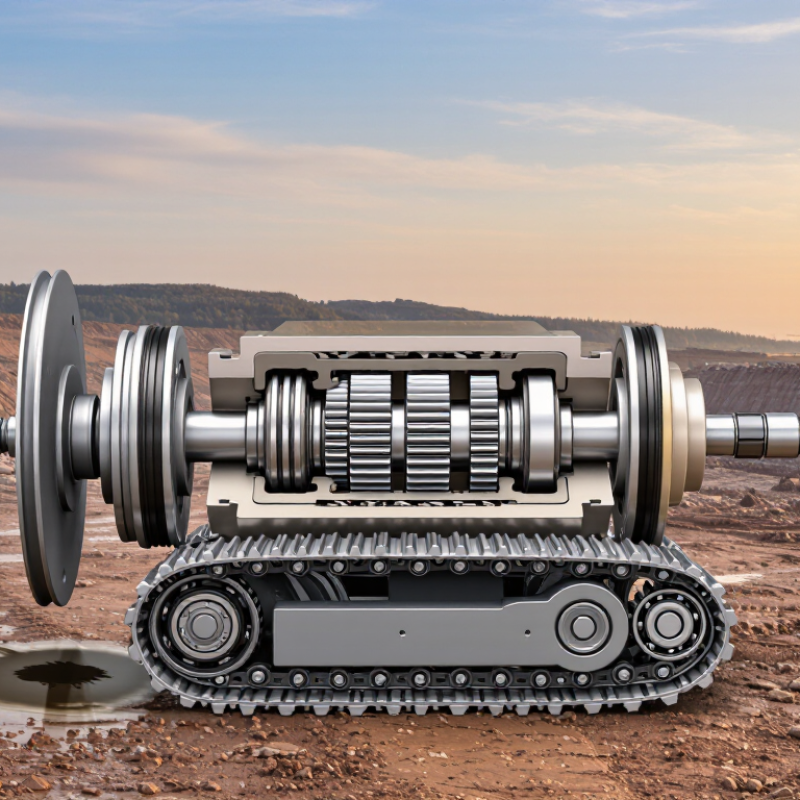
| Hydraulic supply | Delivers pressurized oil from the excavator’s hydraulic system. | Control valves direct oil to the travel motor to move the selected track forward or backward. | Operating pressures of 300–350 bar equal 30–35 MPa. Actual pressure depends on machine design, load, and operating conditions. |
| Hydraulic travel motor | Converts hydraulic energy into rotary motion. | Pressure difference across the motor moves its internal rotating group; reversing oil flow reverses motor rotation. | Axial-piston motors are commonly used in excavator travel drives. Motor speed depends mainly on oil flow and motor displacement. |
| Motor torque | Provides the rotational force needed to drive the track. | Motor torque increases with pressure difference and motor displacement. A simplified relationship is torque ≈ pressure difference × displacement ÷ 2π, adjusted for mechanical efficiency. | Pressure alone does not determine output torque; displacement, efficiency, and losses also matter. |
| Planetary reduction gears | Reduce motor speed and multiply torque. | One or more planetary gear stages transfer motor rotation to the output while providing a compact, high-ratio reduction. | The reduction ratio is designed for the machine’s travel-speed and tractive-force requirements; it varies by drive design. |
| Final-drive housing | Supports and protects the motor and reduction gears. | The sealed housing contains lubricating oil for the gears and bearings and helps keep contaminants out. | Gear lubrication is separate from the motor’s hydraulic oil circuit in many designs. Check the machine’s service instructions for the correct oil and level. |
| Output hub and drive sprocket | Transfer reduced rotation to the crawler track. | The final-drive output turns the sprocket, whose teeth engage the track links and pull the track around the undercarriage. | Sprocket and track-link wear can affect engagement and contribute to uneven or noisy travel. |
| Case-drain circuit | Returns internal leakage oil from the motor to the hydraulic system reservoir. | A dedicated drain line helps prevent excess pressure from building inside the motor case. | Restricted or incorrectly connected case-drain plumbing can cause motor damage. Permitted case pressure and drain flow are model-specific. |
| Travel speed and direction | Control how quickly and which way the track moves. | Oil flow to the motor influences speed; changing the direction of flow reverses rotation. Some drives include a selectable displacement or speed range. | Available speed ranges and control methods vary. The travel control, hydraulic flow, machine load, and terrain all affect actual speed. |
| Pressure relief and overload protection | Help limit pressure spikes and protect hydraulic components. | Relief or cross-port protection may direct oil when pressure exceeds a designed limit, depending on the hydraulic circuit. | Protection settings are machine-specific. Do not assume the typical 300–350 bar operating range is the correct relief-valve setting. |
| Inspection and maintenance | Help maintain reliable travel and identify problems early. | Technicians check for leaks, unusual noise, excess heat, abnormal case-drain flow, and correct gear-oil condition. | Use the machine manufacturer’s service specifications for pressure tests, fluid selection, oil level, and replacement intervals. |
| Note: Pressure, motor displacement, gear ratio, flow, torque, and service limits vary among excavator models. Values and procedures should be confirmed in the applicable machine and component service documentation. |