| Grounding Electrode Rod | Copper-bonded steel, galvanized steel, or stainless steel | Verify the rod diameter and length against the design; drive it vertically where practical; protect the conductor connection from mechanical damage; confirm continuity and measure the completed electrode system with an approved test method. | Inspect exposed connections for looseness, corrosion, and physical damage. Re-test after major electrical work, lightning events, or changes to the site. | Strongly affected by coating thickness, soil chemistry, moisture, stray current, and mechanical damage. Stainless steel is generally preferred for highly corrosive environments when compatible with adjacent metals. | Evaluate corrosion resistance, mechanical strength, availability, installation depth, and whether additional electrodes or bonding are required to meet the project target. | Residential, commercial, utility, and industrial earthing systems where a driven electrode is permitted by local requirements. |
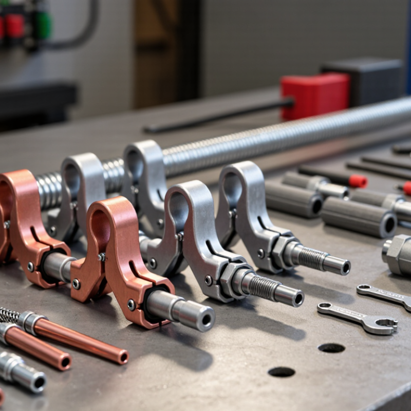
| Grounding Electrode Clamp | Bronze, brass, stainless steel, or listed corrosion-resistant alloys | Use a clamp listed for the electrode and conductor combination. Ensure clean contact surfaces, correct conductor placement, proper tightening, and protection from accidental loosening. Do not bury a connection unless it is approved for direct burial. | Check for corrosion, thermal damage, soil movement, and loss of mechanical tightness. Accessible connections should be included in periodic visual inspections. | Service life depends on alloy compatibility, coating quality, moisture exposure, and the quality of the mechanical connection. Mixed-metal contact can accelerate galvanic corrosion. | A reliable listed connection often provides better lifecycle value than a low-cost clamp that requires frequent replacement or rework. | Connecting grounding conductors to rods, pipes, structural steel, or other permitted electrodes. |
| Grounding Lug and Bonding Connector | Tinned copper, copper alloy, aluminum-compatible alloy, or stainless steel | Confirm compatibility with the conductor and equipment enclosure. Remove paint or oxidation only where required by the installation method; use the specified hardware and tightening torque; verify low-resistance continuity after assembly. | Inspect panels, switchboards, cabinets, and equipment bonds during scheduled maintenance. Look for discoloration, overheating, corrosion, and loose hardware. | Normally durable when correctly sized and protected. Exposure to vibration, heat, chemicals, and repeated maintenance can reduce connection reliability. | Prioritize correct conductor range, vibration resistance, corrosion protection, clear markings, and easy access for inspection. | Bonding equipment enclosures, doors, cable trays, panels, machinery, and structural components. |
| Exothermic Connection | Weld metal, graphite mold, and compatible copper or steel conductors | Confirm that the mold and weld material match the conductor sizes and metals. Keep surfaces clean and dry, follow the approved firing procedure, and visually inspect the completed joint for a complete, solid connection without cracks or excessive porosity. | Usually requires little routine maintenance after a sound installation. Inspect during system audits for mechanical damage, exposed corrosion, or conductor deterioration. | A properly completed connection can provide a permanent, low-maintenance joint, but installation quality depends heavily on preparation, mold condition, and operator training. | Higher initial labor and safety requirements may be justified where buried joints, vibration, fault current, or long service intervals make mechanical retightening impractical. | Permanent buried joints, grid intersections, high-current bonding, and locations where mechanical connections are difficult to access. |
| Grounding Inspection Pit | Polymer concrete, high-strength plastic, concrete, or masonry | Install with a stable base and drainage provisions; keep the cover flush and accessible; prevent standing water where possible; label the pit and ensure the connection can be safely inspected without disturbing the electrode. | Remove debris, check the cover and frame, inspect the visible connection, and verify that water, soil settlement, or traffic has not damaged the assembly. | Durability depends on UV exposure, vehicle loading, freeze-thaw cycles, chemical exposure, and drainage. Covers in traffic areas require an appropriate load rating. | A well-designed pit reduces inspection labor and helps identify corrosion or loose connections before they affect system performance. | Sites requiring accessible testing points, such as commercial facilities, substations, data centers, and lightning-protection systems. |
| Ground Enhancement Material | Conductive concrete, bentonite-based compounds, graphite blends, or other approved conductive backfill | Use only where permitted by the design and local requirements. Follow the specified moisture, mixing, placement, and compaction procedure. Confirm that the material will not create unacceptable corrosion or environmental effects. | Check for drying, washout, settlement, exposure, and changes in soil conditions. Re-test the electrode system rather than assuming the backfill maintains a fixed resistance value. | Performance varies with moisture retention, soil chemistry, freeze-thaw conditions, and installation quality. Some products require periodic assessment in dry or corrosive locations. | Compare installed cost with drilling, additional electrode length, parallel electrodes, or a larger grounding grid. Do not select material based only on an advertised resistance reduction. | High-resistivity soil or restricted sites where conventional electrode expansion is difficult or expensive. |
| Grounding Conductor and Flexible Bonding Strap | Bare copper, tinned copper, copper-clad steel, or flexible braided copper | Verify conductor cross-sectional area, routing, bend radius, support, separation from sharp edges, and connection security. Keep the path as direct as practical and bond all required metallic parts. | Inspect for abrasion, corrosion, overheating, loose fasteners, and damage caused by vibration or movement. Flexible straps should not be sharply bent or used beyond their movement rating. | Depends on current duty, mechanical movement, UV exposure, chemicals, and protection from physical damage. Tinned conductors can be advantageous in humid or marine environments. | Proper sizing and robust routing reduce fault risk, nuisance failures, and future replacement work. The lowest purchase price may not provide the lowest installed cost. | Equipment bonding, door bonding, cable-tray bonding, moving machinery, and vibration-prone installations. |