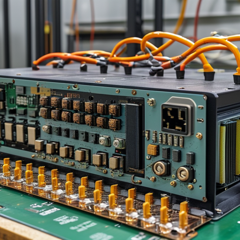
How to Choose a Hybrid Inverter PCB in 2026?

Choosing the right Hybrid Inverter Pcb in 2026 requires more than comparing prices or copper thickness. The board sits at the center of a demanding energy system. It must manage battery storage, solar input, grid interaction, and changing loads without losing control. A poor decision may appear acceptable during factory testing, then fail after months of heat, vibration, and repeated power cycles.

Start with the inverter’s electrical profile. Check maximum voltage, continuous current, surge duration, switching frequency, and isolation requirements. The PCB layout should provide suitable creepage and clearance distances. It should also control electromagnetic interference around high-speed switching devices. Thermal design matters just as much. Large copper areas, thermal vias, airflow paths, and reliable heat-spreading materials can prevent local hot spots near MOSFETs and capacitors. Small details become expensive failures.

Material selection deserves equal attention. High-Tg laminates may support demanding thermal cycles, while controlled impedance can improve signal stability. However, premium materials cannot repair a weak layout. Ask manufacturers for traceability records, inspection results, aging data, and compliance documentation. Verify testing under realistic battery and grid conditions, not only ideal laboratory loads. Standards and certifications should match the target market and product design.

There is no universal best board.

An experienced team should review supplier capability, repair access, production consistency, and long-term component availability. Initial assumptions can be wrong, especially when a prototype performs well but lacks field endurance. For this reason, compare measured evidence with datasheets, inspect failure history, and leave room for design revision. The strongest Hybrid Inverter Pcb is not simply the most advanced option. It is the one that remains safe, stable, serviceable, and dependable throughout its expected operating life.

How to Choose a Hybrid Inverter PCB in 2026?

Define the Role and Requirements of a Hybrid Inverter PCB

How to Choose a Hybrid Inverter PCB in 2026?

A hybrid inverter PCB manages power between solar panels, batteries, loads, and the utility connection. Its role is more than switching current. It also controls charging, conversion, protection, communication, and fault responses. Define these functions before comparing board specifications. A 48 V battery system may need high-current copper paths, accurate voltage sensing, and controlled inrush protection. A grid-connected design requires isolation, reliable gate control, and carefully managed electromagnetic interference. Thermal performance matters too. Check heat around MOSFETs, transformers, connectors, and current sensors. Small hot spots can become expensive failures.

Tips: Write a requirement sheet first. Include input range, output power, switching frequency, operating temperature, cooling method, and expected service life. Ask for test evidence, not only impressive ratings. Review creepage, clearance, overcurrent protection, and communication interfaces. Examine whether the PCB supports firmware updates and clear fault reporting. These details often decide whether maintenance is simple or frustrating.

In practical design reviews, a high-rated PCB is not always the best choice. Its connectors may be weak, or its thermal design may rely on ideal airflow. That assumption deserves challenge. I would inspect waveforms under light and peak loads, then check temperature after repeated cycles. Efficiency should be measured across realistic battery voltages, not one convenient point. Leave room for uncertainty. Field conditions are rarely perfect, and a design that ignores dust, vibration, or aging may look excellent only on paper.

Compare PCB Materials, Layer Design, and Electrical Ratings

How to Choose a Hybrid Inverter PCB in 2026?

Compare PCB Materials, Layer Design, and Electrical Ratings

A hybrid inverter PCB must manage battery power, grid input, and solar energy without wasting heat. Material selection matters from the first design review. Standard FR-4 works for many systems, but high-Tg FR-4 offers better stability near hot switching components. Look for controlled dielectric thickness and dependable insulation performance. Cheap laminate can create hidden failures.

Copper weight also deserves practical attention. Two-ounce copper handles higher current better than one-ounce copper, but it increases cost and manufacturing difficulty. Use wider traces for battery paths and short routes for high-current loops. Keep sensitive measurement signals away from switching nodes. Small details matter.

A four-layer board often provides a useful balance between cost and performance. One layer can carry power, while another supports a continuous ground plane. Internal planes reduce noise and improve heat spreading. More layers may help complex designs, but they do not automatically improve reliability. I have seen crowded six-layer layouts perform worse than clean four-layer boards.

Electrical ratings must match real operating conditions, not only nominal values. Check continuous current, surge current, maximum voltage, creepage, and clearance. Include temperature rise during enclosed operation. Components rated at room temperature may derate sharply near 70°C. That part is easy to overlook. Verify insulation distances against the target market’s safety requirements. Test prototypes under overload, rapid switching, and repeated thermal cycling. A design that passes one bench test may still need revision.

Evaluate Thermal Management, Protection, and Reliability Features

How to Choose a Hybrid Inverter PCB in 2026?

Thermal management should be checked before switching speed or connector count. The IEA PVPS Trends in Photovoltaic Applications 2024 report recorded 456 GW of new solar capacity in 2023. That growth increases demand for compact, continuously loaded power electronics. Choose a PCB with wide copper paths, controlled heat spreading, and verified thermal vias. Inspect the layout around MOSFETs, magnetic components, and capacitors. A small hotspot can shorten service life.

Ask for thermal images under rated load, not only laboratory efficiency figures. The NREL PV Inverter Reliability Workshop materials identify thermal stress, capacitor aging, and solder fatigue as recurring reliability concerns. Select capacitors with suitable ripple-current ratings and temperature margins. Include fan-failure detection, controlled derating, and realistic enclosure tests. Quiet operation is useful, but silent overheating is not.

Protection must cover more than overcurrent. Check surge protection, short-circuit response, reverse-polarity control, isolation monitoring, and safe shutdown behavior. Confirm creepage and clearance against the intended voltage and pollution environment. Certification evidence should match the final PCB revision. It sounds obvious. It is often missed.

For reliability, request temperature-cycling, humidity-bias, vibration, and power-cycling results. Ask whether tests used production samples. A polished report can still hide weak assumptions. I would also review field-return data, even when the sample size is uncomfortable. No design is perfect. A repairable layout, clear fault logging, and replaceable high-stress components can matter more than a small efficiency gain.

Check Compatibility, Certifications, Manufacturing Quality, and Cost

How to Choose a Hybrid Inverter PCB in 2026?

Choosing a hybrid inverter PCB starts with compatibility, not the lowest quotation. Check the DC voltage range, battery chemistry, charging current, grid frequency, and communication protocols. A board may fit mechanically yet fail during cold starts or sudden load changes. The IEA Renewables 2024 report forecasts global renewable capacity could reach 10,800 GW by 2030. That growth increases demand for flexible power electronics. Verify firmware support, isolation distances, connector ratings, and thermal margins. Small mismatches become expensive field failures.

Certification requires careful checking. Ask for test evidence covering IEC 62109-1, IEC 62109-2, IEC 62477-1, and relevant IEC 61000 EMC requirements. Certification is not a logo. It should identify the tested configuration and production site. NREL reliability research repeatedly identifies thermal stress, capacitors, solder joints, and environmental exposure as inverter failure concerns. Request temperature-cycle results, humidity testing, X-ray inspection records, and traceability for every PCB batch. I have seen attractive samples perform well briefly, then drift after repeated heat cycles.

Manufacturing quality also affects cost. Examine copper thickness, laminate rating, component derating, automated optical inspection, and functional testing. The IEA estimates that renewables added about 510 GW globally in 2023, raising pressure for scalable production. Compare total cost, including testing, warranty reserves, firmware updates, and field replacement. A cheaper PCB can become costly after one service visit. I still leave design margin for uncertain battery behavior; that may look excessive, but removing it too early is a risky saving.

Select and Validate the Best Hybrid Inverter PCB for 2026

How to Choose a Hybrid Inverter PCB in 2026?

Select and validate the best hybrid inverter PCB by matching it to real operating conditions, not headline specifications. IRENA’s Renewable Capacity Statistics 2025 reported 585 GW of renewable capacity additions in 2024. That growth increases demand for compact, efficient, and serviceable power electronics. A suitable PCB should support the inverter’s battery voltage, maximum current, switching frequency, and expected temperature range. Check creepage, clearance, insulation, surge protection, and connector ratings against IEC 62109 and relevant EMC requirements. Small gaps can create large field failures.

Thermal validation deserves practical testing. Measure hotspot temperatures near MOSFETs, transformers, busbars, and gate-driver circuits under continuous load. Use thermal cycling, humidity exposure, vibration checks, and controlled overload tests. The IEA’s Renewables 2024 report projects global renewable capacity could reach nearly 5,500 GW by 2030. Hybrid systems will therefore face longer duty cycles and more variable operating profiles. Design margin matters.

Do not trust a perfect spreadsheet.

I once accepted a PCB with excellent laboratory efficiency but weak cooling around the switching stage. It passed quickly, yet its enclosure became uncomfortable during sustained operation. Recheck airflow, copper thickness, solder quality, creepage after contamination, and protection response. Review test records, component traceability, failure analysis, and production consistency. A pilot batch can reveal assembly defects that simulations miss. Validation is never finished too early.

How to Choose a Hybrid Inverter PCB in 2026? - Select and Validate the Best Hybrid Inverter PCB for 2026
Selection Dimension Recommended 2026 Reference Minimum Acceptance Criteria Validation Method Typical Risk if Underspecified
System Voltage Class PCB creepage, clearance, insulation system, and component voltage ratings must match the maximum working voltage plus transient margin. Review the electrical safety design against IEC 60664-1 and the applicable inverter safety standard. Confirm worst-case surge and pollution-degree assumptions. Insulation breakdown, arcing, electrical shock hazard, or premature component failure.
Continuous Current Capability Temperature rise remains within the component, laminate, connector, and enclosure limits at maximum rated load. Perform current-density calculations and test at full load in the final enclosure. Measure copper, connector, busbar, and terminal temperatures using thermocouples or thermal imaging. Excessive heating, solder-joint fatigue, voltage drop, and reduced service life.
Peak and Fault Current Protection devices interrupt fault energy before PCB traces, vias, or terminals exceed their safe operating limits. Conduct controlled overload, short-circuit protection, and current-interruption tests with safety containment and calibrated instruments. Trace fusing, carbonization, connector welding, or damage to switching devices.
Power Semiconductor Layout Gate-loop inductance, switching-node area, and parasitic coupling are minimized according to the switching frequency and device technology. Use oscilloscope measurements with suitable differential and current probes. Check overshoot, ringing, dead time, gate voltage, and switch-node behavior at minimum and maximum DC-link voltage. Excessive EMI, device overstress, false turn-on, unstable switching, or reduced efficiency.
Thermal Management All critical components remain below their rated temperature during continuous full-load operation and defined overload conditions. Run thermal testing at minimum and maximum ambient temperatures. Record steady-state temperatures and compare calculated junction temperatures with datasheet limits. Thermal derating, nuisance shutdowns, accelerated aging, or thermal runaway.
PCB Material and Stack-Up Material Tg, decomposition temperature, dielectric strength, copper weight, and surface finish are documented and traceable. Review material certificates, stack-up drawings, impedance data where relevant, and incoming inspection records. Confirm compliance with the required flammability rating. Delamination, dielectric failure, dimensional instability, or inconsistent electrical performance.
Creepage and Clearance All high-voltage nets, mounting hardware, heatsinks, connectors, slots, and test points meet the applicable safety requirements. Perform a layout rule audit and physical inspection. Include worst-case tolerances, contamination, coating limitations, and manufacturing registration errors. Arcing, tracking, failed safety testing, or unsafe field operation.
EMI and EMC Readiness Noise-control components are placed close to the source and have suitable voltage, current, pulse, and temperature ratings. Conduct pre-compliance conducted-emission, radiated-emission, EFT, surge, and ESD testing using the final cables, enclosure, firmware, and operating modes. Certification failure, communication errors, radio interference, or unstable control behavior.
Isolation and Control Interfaces Isolation voltage, creepage, clearance, common-mode transient immunity, and maximum switching frequency meet the system requirements. Check isolation-barrier documentation and perform dielectric withstand, insulation-resistance, and common-mode transient tests as applicable. Control malfunction, loss of protection, communication failure, or hazardous touch voltage.
Energy Storage and DC-Link Components Ripple-current heating and transient voltage remain within component limits during charging, discharging, regeneration, and fault conditions. Measure capacitor ripple current and temperature during representative duty cycles. Test pre-charge timing, discharge voltage, and abnormal operating conditions. Capacitor venting, fuse failure, excessive DC-link ripple, or dangerous residual voltage.
Protection and Measurement Accuracy Sensor accuracy, offset, bandwidth, and fault thresholds remain within the control-system safety budget across temperature and supply variation. Use calibrated sources to test threshold accuracy, response time, fault latching, reset behavior, and single-point sensor failures. Delayed shutdown, nuisance trips, inaccurate power control, or undetected hazardous conditions.
Manufacturing Quality Fabrication and assembly processes follow the applicable IPC workmanship and acceptance requirements agreed in the purchase specification. Review first-article records, AOI and electrical-test results, solderability data, process capability, and corrective-action procedures. Intermittent faults, hidden solder defects, field returns, and inconsistent production performance.
Environmental Reliability Conformal coating, sealing, component derating, and corrosion protection are applied only where compatible with thermal and electrical requirements. Perform temperature cycling, damp-heat, vibration, mechanical shock, and accelerated-life tests using the final assembly and enclosure. Corrosion, cracking, moisture-related leakage, connector failures, or intermittent operation.
Serviceability and Lifecycle Critical components have approved second sources or a documented replacement strategy without changing safety or thermal performance. Review service procedures, diagnostic coverage, component lifecycle data, firmware compatibility, and change-control records. Long repair times, redesign costs, production interruptions, or unsupported field units.
Final Selection Gate No unresolved critical or high-risk findings remain in the design verification report. Complete a formal design review, compliance matrix, prototype test report, production pilot, and corrective-action closure before release. Successful laboratory results may not translate into reliable field performance.
Reference values are engineering selection criteria for hybrid inverter PCB evaluation. Final requirements must be calculated and verified against the inverter topology, rated power, battery voltage, grid requirements, installation environment, applicable regulations, and the complete system safety design.
Find the Right Repair Product for Your Project

Need to find the most appropriate product for the needs of your project? We can help because we have over 70 years of experience servicing the industry with every kind of project, from Do-it-yourself projects to large skyscrapers. Package Pavement has the experience, the knowledge and the products to help every project succeed.

Quikrete Repair Products
Legend
Package Pavement has two convenient locations in Stormville, NY (Dutchess County) and Ravena, NY (Greene County) to serve the Northeastern Region with bagged concrete, blacktop, mortar, and repair products. This map gives a general idea of where we service and the product lines we offer.
Package Pavement Products
Quikrete Products
Spec Mix Products
map

Our Brands Websites