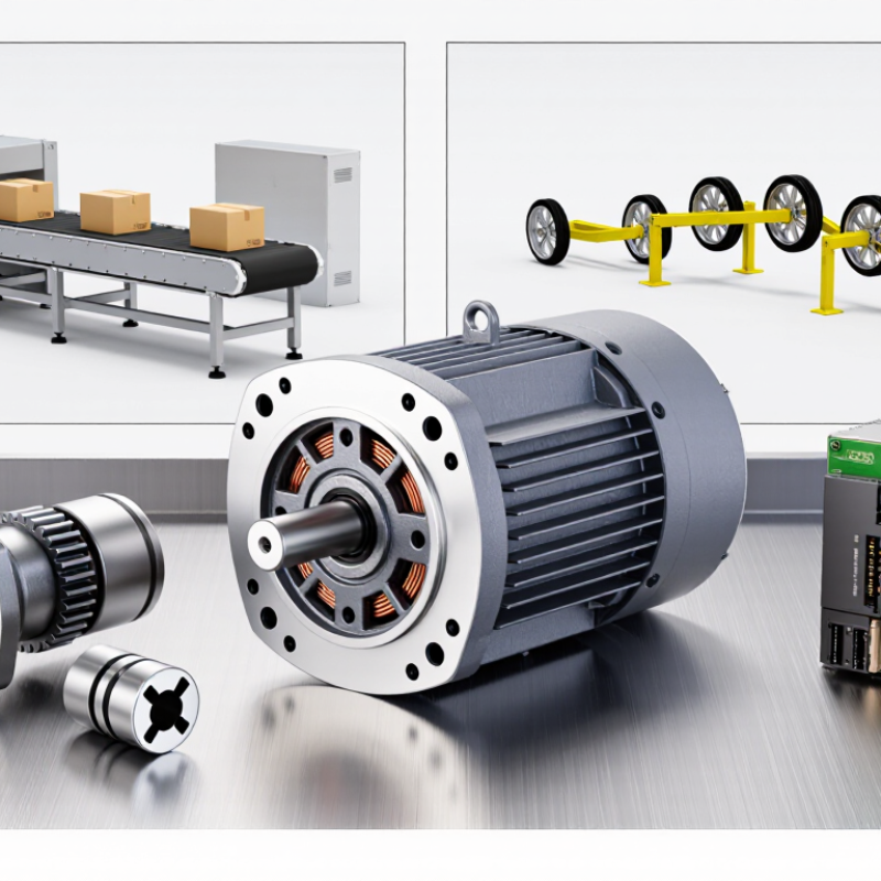
| Conveyor drive | Approximately 2–10 N·m at the motor shaft; more may be required at the conveyor roller after gearing. | About 300–1,500 rpm at the motor; roller speed depends on the reduction ratio and roller diameter. | Often continuous or long-duration operation, with extra torque needed during startup and when the belt is loaded. | Select a DC bus compatible with the system; define speed regulation, reversing, and braking needs. | Belt load, roller diameter, acceleration time, starts per hour, ambient temperature, and allowable speed variation. |
| Mobile robot or AGV traction | A planning range of 20–100 N·m at a geared wheel output may be appropriate for some units; calculate from vehicle mass, wheel radius, grade, and acceleration. | Typically low wheel speed, with motor speed determined by the gear ratio and required travel speed. | Intermittent travel with frequent starts, stops, turns, and short acceleration peaks. | Battery voltage range, regenerative braking behavior, encoder feedback, and traction-control interface. | Vehicle mass, wheel size, maximum grade, desired acceleration, duty cycle, tire grip, and peak current limit. |
| Pump drive | Approximately 0.5–5 N·m at the motor shaft for some small pump duties; actual torque depends on pump type, pressure, flow, and speed. | Often about 1,000–3,000 rpm, subject to the pump’s specified operating range. | May be continuous; startup torque and operation against pressure can affect motor sizing. | Define DC supply, speed-control method, overload response, and whether closed-loop speed regulation is needed. | Pump type, required flow and pressure, fluid temperature, viscosity, inlet conditions, and permissible noise. |
| Linear actuator or positioning axis | Approximately 10–80 N·m at a geared output is a possible planning range; screw lead, transmission efficiency, and load determine the required value. | Usually low output speed; motor speed is set by the gearbox and the required linear travel rate. | Intermittent motion with acceleration and holding periods; a brake may be needed for loads that can back-drive the mechanism. | Define position feedback, limit switches, holding strategy, and controller current limits. | Load, stroke, screw lead, required travel time, accuracy, backlash, holding duration, and mounting orientation. |
| Mixer or agitator | Approximately 5–30 N·m at the motor shaft may suit some small systems; viscous or changing loads can require substantially more torque. | Often about 100–1,000 rpm, depending on the mixing process and any reduction gearing. | May run continuously or in batches; startup with material in the vessel can create a demanding load. | Specify adjustable speed, overload handling, and enclosure protection appropriate to the installation. | Material viscosity, batch size, impeller geometry, startup condition, cleaning method, and required speed range. |