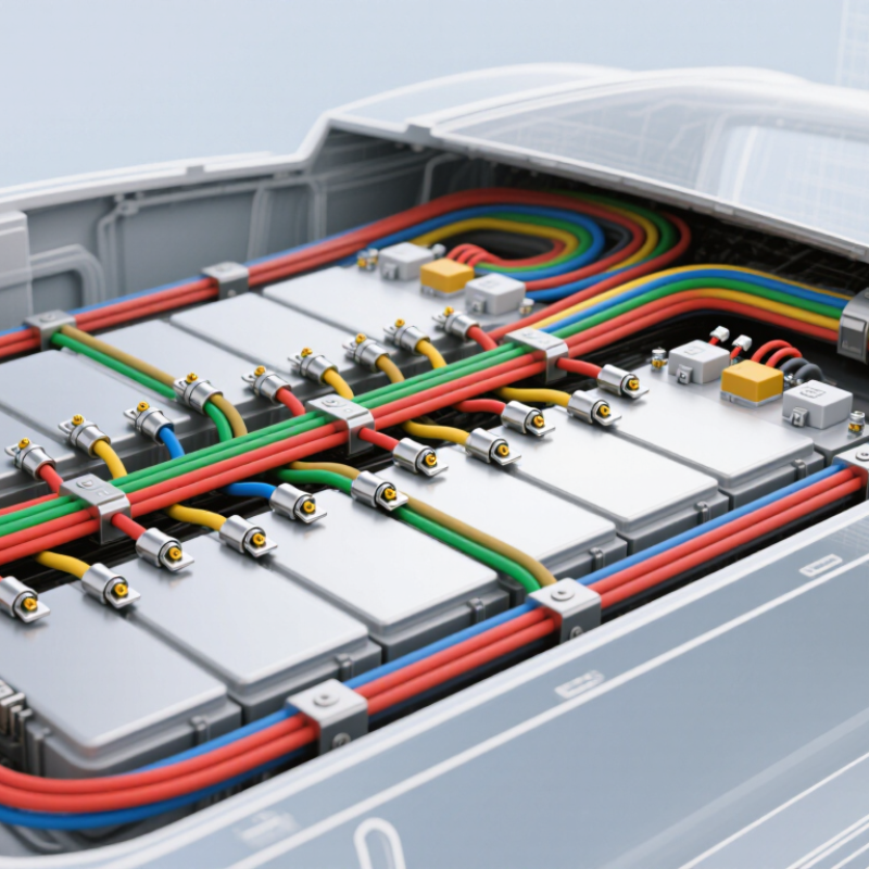
| Cell Voltage Tap Wires | Carry individual cell or cell-group voltage signals to the battery-monitoring electronics. | Cell voltage, voltage imbalance, overvoltage, and undervoltage conditions. | Cell terminals, busbars, module monitoring boards, or a centralized BMS measurement connector. | Correct wire sequence, insulation, creepage distance, strain relief, and protection against accidental short circuits are essential. |
| Temperature Sensor Wires | Connect temperature sensors to the BMS for thermal condition monitoring. | Cell, module, busbar, connector, or enclosure temperature. | Negative-temperature-coefficient thermistors or other approved temperature sensors and BMS input channels. | Sensor placement should represent the hottest areas; wires should be routed away from high-current conductors where practical. |
| Current Sensor Wiring | Transmit battery-current measurements to the BMS. | Charge current, discharge current, current direction, and accumulated charge flow. | Shunt, Hall-effect sensor, or other isolated current-measurement device. | Signal polarity, sensor isolation, low-noise routing, and secure low-voltage connectors help maintain measurement accuracy. |
| Contactor Control Wires | Allow the BMS to open or close high-voltage switching devices. | Battery connection status, pre-charge operation, charge enable, and discharge enable. | Positive contactor, negative contactor, pre-charge contactor, and their driver circuits. | The harness must support the specified coil voltage and current while maintaining separation from high-voltage power paths. |
| Pre-Charge Circuit Wires | Support controlled charging of the external DC-link capacitors before the main contactors close. | Pre-charge timing, voltage rise, and abnormal inrush-current conditions. | Pre-charge contactor, resistor, voltage measurement points, and BMS control circuitry. | Incorrect sequencing can cause excessive inrush current or prevent the battery from connecting safely. |
| High-Voltage Interlock Loop Wires | Provide a continuity-check circuit for high-voltage covers, connectors, and service-access points. | Open connectors, removed covers, or compromised enclosure access points. | Interlock switches, high-voltage connectors, service disconnects, and BMS or vehicle control inputs. | A detected open circuit should trigger a defined protective response, such as opening the contactors. |
| Low-Voltage Power Wires | Supply operating power and reference connections to BMS electronics and sensors. | BMS operating status, sensor reference levels, and internal diagnostic conditions. | Auxiliary battery, regulated power supply, BMS controller, monitoring boards, and sensor circuits. | Fuse protection, correct polarity, voltage-drop control, and reliable grounding are required. |
| Communication Wires | Exchange measurements, warnings, limits, and control commands between BMS modules and external controllers. | State of charge, state of health, temperature data, fault codes, charge limits, and contactor requests. | BMS controller, monitoring units, charger, inverter, vehicle controller, or energy-management system. | Bus termination, twisted-pair routing where applicable, shielding, signal integrity, and communication protocol compatibility matter. |
| Shielding and Reference Conductors | Reduce electromagnetic interference and provide controlled signal reference paths. | Stable low-level voltage, current, temperature, and communication signals. | Cable shields, signal grounds, chassis reference points, and BMS connector terminals. | Shield termination and grounding should follow the system's electrical and electromagnetic-compatibility design. |
| Connectors and Terminals | Create detachable electrical and mechanical interfaces between the harness, cells, sensors, modules, and control electronics. | All signals and power paths carried by the harness. | Cell tabs or busbars, sensor leads, BMS boards, contactors, current sensors, and external system interfaces. | Keying, locking, touch protection, sealing, terminal retention, corrosion resistance, and serviceability are important. |
| Protective Sleeving and Routing Features | Protect conductors from abrasion, heat, vibration, moisture, and incorrect movement. | Harness integrity and long-term signal reliability. | Braided sleeving, conduit, clips, grommets, strain reliefs, labels, and fastening points. | Routing should avoid sharp edges, hot surfaces, moving parts, and unnecessary proximity to high-current or high-noise conductors. |