| Plate-Fin Heat Exchanger | Main cryogenic heat exchanger, feed-gas cooling, liquefaction and mixed-refrigerant temperature exchange | Approximately −170°C to +65°C, depending on the process stream and design | Commonly about 20–100 bar(g); project-specific designs may differ | Aluminum brazed core, aluminum fins and headers; stainless-steel connections may be used | Very high heat-transfer area per unit volume, compact footprint, low temperature approach and efficient multistream operation | Sensitive to heavy hydrocarbons, water, carbon dioxide and particulates; requires highly effective upstream purification | Large-scale LNG liquefaction and cryogenic gas-processing plants with clean, dry feed gas |
| Printed Circuit Heat Exchanger | High-pressure gas cooling, compact cryogenic service and heat recovery in demanding process layouts | Approximately −200°C to +800°C, subject to materials, joining method and design conditions | Can be designed for high-pressure service, often above 100 bar(g), subject to applicable code | Stainless steel, nickel alloys or other cryogenic-compatible alloys | High pressure and temperature capability, compact size, strong mechanical integrity and good resistance to thermal cycling | Higher fabrication complexity and cost; channel blockage can be difficult to detect or repair | High-pressure LNG, natural-gas processing, hydrogen and other compact cryogenic applications |
| Coiled-Wound Heat Exchanger | Main cryogenic heat exchange, multistream LNG liquefaction and large refrigeration duties | Approximately −180°C to +100°C, depending on process configuration | Often around 30–90 bar(g) on the process side; design pressure varies by stream | Aluminum or stainless-steel tubes, shell and headers selected for cryogenic compatibility | Handles multiple streams in one vessel, accommodates thermal contraction and supports large LNG capacities | Large equipment size, specialized manufacturing and potentially complex inspection and maintenance | Large baseload LNG plants requiring integrated multistream cooling and liquefaction |
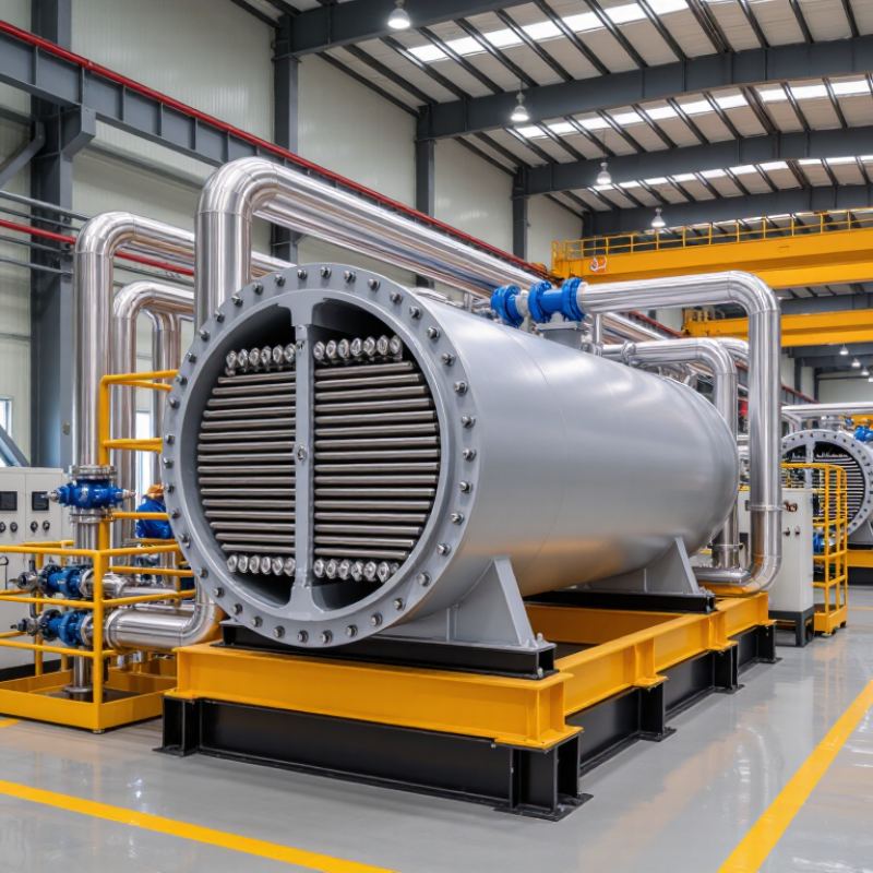
| Shell-and-Tube Heat Exchanger | Feed-gas precooling, compressor intercooling, boil-off-gas warming, utility cooling and LNG subcooling | Approximately −160°C to +400°C, depending on materials and service | Commonly 10–150 bar(g); higher pressures are possible with specialized design | Carbon steel, stainless steel, low-temperature steel, nickel alloys or aluminum alloys | Robust, familiar design, easier mechanical cleaning and broad applicability across process units | Larger footprint and lower heat-transfer compactness than brazed or printed-circuit designs | Utility systems, pretreatment, compressor stations and duties with fouling or high mechanical-cleaning requirements |
| Brazed Plate Heat Exchanger | Refrigerant cooling, glycol or water circuits, compact utility heat exchange and small-scale LNG systems | Typically about −50°C to +200°C; the actual limit depends on brazing material and design | Often up to approximately 30–40 bar(g), subject to the selected construction and code requirements | Stainless-steel plates with copper- or nickel-based brazing material | Compact, efficient, lightweight and economical for clean single-phase or two-phase utility duties | Limited cleanability, restricted repair options and unsuitable for contaminated natural-gas feed streams | Packaged LNG, fueling stations and clean refrigeration or utility circuits |
| Air-Cooled Heat Exchanger | Compressor discharge cooling, gas aftercooling and hydrocarbon-condensate cooling where cooling water is limited | Usually approximately 20°C to 180°C; not intended for primary LNG cryogenic duty | Commonly 10–100 bar(g), depending on gas composition and equipment design | Carbon steel, stainless steel, aluminum fins and corrosion-resistant alloys where required | Does not require cooling water, reduces water-treatment demand and is suitable for remote facilities | Performance depends on ambient temperature, fan power and available plot area; noise may require control | Upstream and auxiliary natural-gas-processing services rather than core liquefaction |
| Regenerative Heat Exchanger | Cold-box heat recovery, waste-gas warming and temperature recuperation in cryogenic cycles | Approximately −180°C to +300°C, depending on matrix material and operating cycle | Typically low to moderate pressure, often below 30 bar(g), with pressure drop carefully controlled | Aluminum, stainless steel or ceramic matrix materials, depending on the application | High thermal effectiveness and reduced equipment count in selected cryogenic process arrangements | Potential cross-contamination between streams and moving or switching components may increase operational complexity | Specialized cryogenic cycles where stream separation and contamination control are properly managed |