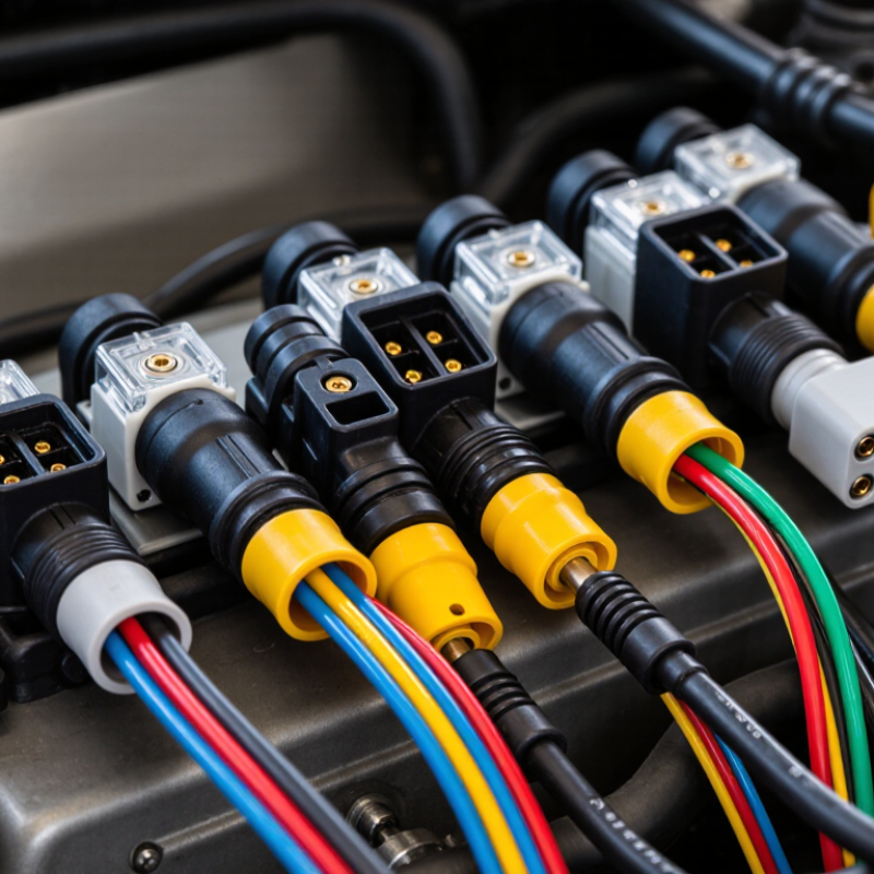
| Sealed 1-cavity connector | Single-wire circuits, such as some switches, grounds, or auxiliary connections | Check terminal style, wire range, locking method, and whether the circuit needs a dedicated return wire. | Choose a sealed design where splash, dirt, or moisture is expected. | Assuming one cavity means the connector can carry any current; terminal and wire ratings still apply. |
| Sealed 2-cavity connector | Two-wire sensors, small actuators, and simple power-and-return circuits | Match cavity count, terminal size, wire gauge, circuit polarity, and the vehicle-side mating half. | Useful in exposed areas when the seal and temperature range suit the installation. | Using an unsealed counterpart in a wet or dirty location. |
| Sealed 3-cavity connector | Many three-wire sensors using supply, signal, and ground connections | Confirm the pinout from the vehicle wiring diagram; cavity positions are not universally assigned. | Check seal compatibility with the wire insulation diameter and connector housing. | Matching only the number of wires while overlooking pin assignment or sensor voltage. |
| Sealed 4-cavity connector | Compact sensor, ignition, or small lighting assemblies with multiple circuits | Verify terminal gender, keying, pinout, wire range, and any circuit-specific current requirements. | Use an appropriate seal and temperature-rated materials near the engine or exterior. | Forcing a similar-looking connector with different keying or terminal layout. |
| Unsealed 2-cavity connector | Low-current interior circuits in protected locations, such as some switches or trim components | Confirm the connector is intended for the location and that its terminals suit the wire gauge. | Best suited to dry, protected areas away from road spray and condensation. | Installing an unsealed connector in an exposed engine-bay or underbody location. |
| Sealed 6-cavity connector | Multi-circuit lighting, body, or sensor harness branches | Compare the full pinout, populated cavities, terminal sizes, and available space for the wire bundle. | Consider vibration, water exposure, and strain relief at the harness entry. | Leaving unused cavities without the specified cavity plugs in a sealed housing. |
| Sealed 8-cavity connector | Door, body, and accessory harness connections with several low- or moderate-current circuits | Check cavity numbering, terminal retention, wire routing, and whether circuits share a common ground. | For doors, account for repeated movement and protect the harness from chafing. | Ignoring flex and abrasion where the harness passes through a moving panel. |
| Sealed 12-cavity connector | Higher-density body or engine-harness branches carrying multiple separate signals and feeds | Use the correct cavity map and terminal families; confirm each circuit’s wire and terminal requirements individually. | Match the housing, seals, and materials to the local temperature and moisture conditions. | Treating every cavity as interchangeable when terminal sizes or circuit functions differ. |
| 2-cavity high-current connector | Higher-load components such as some fans, pumps, or auxiliary power devices | Size terminals and wire for the circuit load, run length, ambient temperature, and overcurrent protection. | Check heat exposure, vibration resistance, and whether the connection needs environmental sealing. | Choosing by cavity count alone; a small two-way connector may not be suitable for a high-load circuit. |
| Inline multi-cavity harness connector | Joining a removable component harness to a vehicle wiring branch | Match housing keying, terminal family, pinout, wire ranges, and service access requirements. | Secure the harness to limit vibration and prevent tension on the terminals. | Mixing connector halves that appear compatible but use different terminals or retention features. |